Standard wall thickness on a plan is the sum of the layers, never a round number or the stud's nominal size. Picture a fit-out plan where the stud partitions went in at a round 100 mm. A 2x4 with 1/2 in board each side builds to 114 mm, and the difference comes out of the rooms on either side.
The sections that follow build each thickness from published component sizes. Stud partitions use US lumber and board sizes. Masonry uses Approved Document A for England. Then they cover which face a dimension measures to, and how to keep every wall of one kind the same.
Key takeaways
- Draw each wall at the sum of its layers: the core plus every lining on both faces.
- A nominal 2x4 is a size name, not a measurement. Draw the dressed stud width, then add the board you specify.
- In England, Approved Document A sets minimum leaf, cavity and solid wall thicknesses for some buildings. Treat them as a floor under the engineer's design.
- Write on the drawing whether dimensions run to the structural face or the finish. Mixing the two without a note shifts room sizes.
- Fix one thickness and one alignment rule per wall type, so every wall of that kind draws the same.
Standard wall thickness at a glance
The drawn thickness of a wall is its core plus every layer fixed to it. The table sums sourced sizes for common stud partitions and gives the masonry minimums for England.
| Wall | Layers | Drawn thickness | Basis |
|---|---|---|---|
| 2x4 stud partition | Stud plus 1/2 in board each side | 4-1/2 in (114 mm) | PS 20-20 and USG sizes |
| 2x4 stud partition | Stud plus 5/8 in board each side | 4-3/4 in (121 mm) | PS 20-20 and USG sizes |
| 2x6 stud framing | Stud plus 1/2 in board each side | 6-1/2 in (165 mm) | PS 20-20 and USG sizes, framing and linings only |
| Cavity wall, England | Two leaves and a cavity | 230 mm minimum before linings, with thicker leaves where Table 3 asks for 290 mm | Approved Document A, Section 2C |
| Solid external, compartment or separating wall, England | Brick or block | 190 mm, or 290 mm for the lowest one or two storeys of the taller or longer Table 3 walls | Approved Document A, Table 3, walls up to 12 m high and 12 m long |
The stud rows cover framing and linings only. Anything else in the wall, such as insulation, sheathing or a service void, adds to the sum. The masonry rows are floors set in guidance, not the figure for every job.
Nominal vs actual: why a 2x4 is not 4 inches
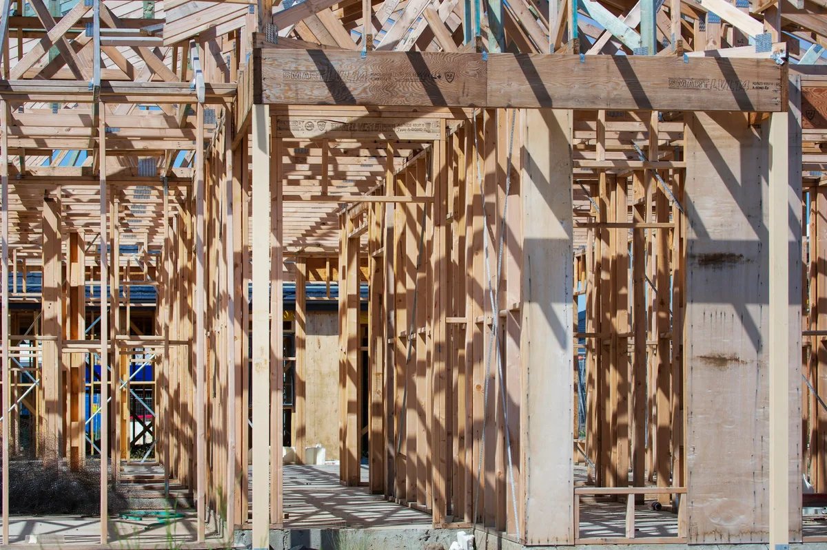
Under PS 20-20, the American Softwood Lumber Standard, a nominal 2x4 has a minimum dressed dry size of 1-1/2 by 3-1/2 in. So a stud wall starts at 3-1/2 in, not 4. Table 3 of the standard lists nominal sizes beside dressed sizes, in inches and millimetres.
Wider nominal sizes lose width the same way, as the chart shows.
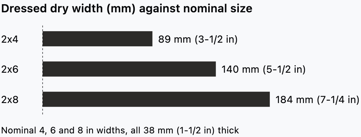
The nominal name is a label, and the drawing needs the dressed figure. The standard tells you what a piece of lumber measures. What thickness a wall must be is a separate decision, made from the stud you specify and the linings it carries.
When a set mixes 2x4 and 2x6 walls, give each its own entry in the wall list. A plan that draws both at one rounded figure loses the difference between 89 and 140 mm.
Interior partitions: stud plus board each side
USG lists its Sheetrock UltraLight panels at 1/2 in (12.7 mm) for interior walls and ceilings. Worked example: a 2x4 stud with one panel each side gives 3-1/2 + 1/2 + 1/2 = 4-1/2 in. In millimetres, that is 89 + 12.7 + 12.7 = 114.4 mm, drawn as 114.
Board thickness moves that figure. The same maker's Sheetrock Firecode X panels are 5/8 in (15.9 mm) Type X panels that comply with ASTM C1396. With one of those each side, the same stud gives 4-3/4 in, or 121 mm.
So the board in the specification decides the partition, not the stud alone. Take the thickness from the board you specify, and redraw the wall when the specification changes. Two layers of board on a face add both layers to the sum. An exterior wall adds sheathing, cladding and whatever the thermal design needs, so build its thickness from those layers too.
Masonry walls in England: what Approved Document A sets
Masonry minimums in England come from guidance, and they apply to a defined group of buildings. Approved Document A is the guidance on the structural elements of buildings in England. Its Section 2C applies to residential buildings of not more than three storeys, small single-storey non-residential buildings and small annexes to residential buildings. For those buildings, all cavity walls should have leaves at least 90 mm thick and cavities at least 50 mm wide.
Worked example: two minimum leaves and a minimum cavity give 90 + 50 + 90 = 230 mm. That is the masonry alone, before any lining or insulation choice. Treat it as the floor of the build-up, and take the real leaf and cavity sizes from the engineer and the thermal design.
Solid walls face two tests. Solid coursed brick or block walls should be at least as thick as 1/16 of the storey height. Table 3 then sets minimum thicknesses for certain external, compartment and separating walls.
Table 3 covers walls up to 12 m high and 12 m long. A wall up to 3.5 m high and 12 m long needs 190 mm for its whole height. So does a wall between 3.5 and 9 m high and up to 9 m long. A wall 3.5 to 9 m high and 9 to 12 m long needs 290 mm for the lowest storey. So does a wall 9 to 12 m high and up to 9 m long. A wall 9 to 12 m high and 9 to 12 m long needs 290 mm for the lowest two storeys. Above those storeys, each needs 190 mm. Walls beyond those bounds fall outside Table 3.
The two tests give different figures for the same wall, and the larger one is the figure to meet. Take a 2.4 m storey as an example: 1/16 of it is 150 mm, under the 190 mm in Table 3. For an external wall of that height and up to 12 m long, the table governs.
Cavity walls meet Table 3 through a sum, for external, compartment and separating walls. The two leaves plus 10 mm should not be less than the solid wall figure for the same height and length. Two minimum leaves give 90 + 90 + 10 = 190 mm. That meets the row for a wall up to 3.5 m high and 12 m long.
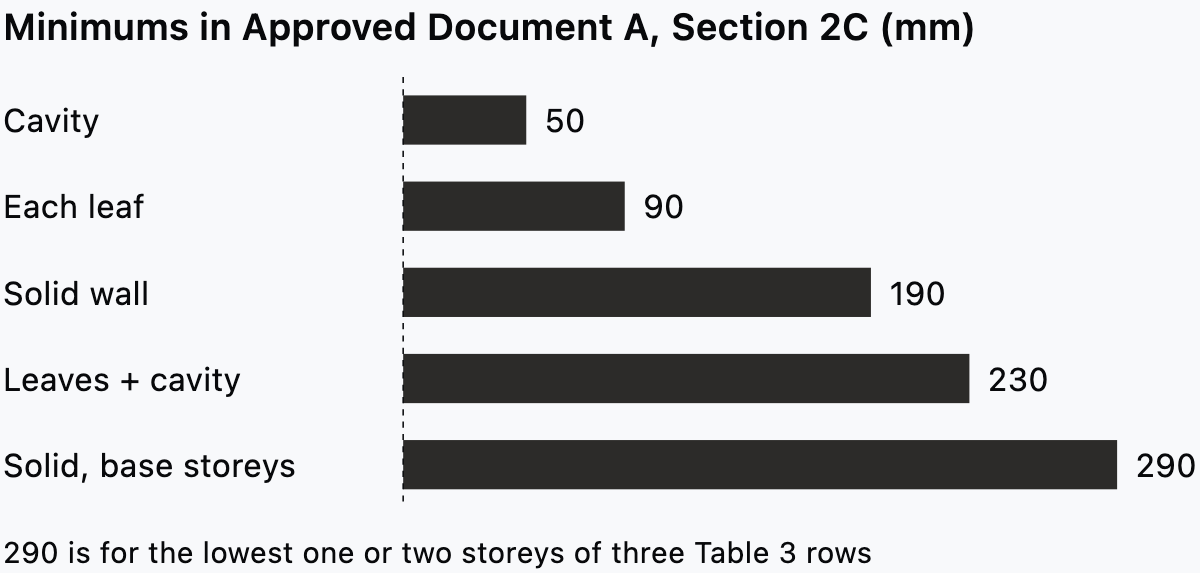
In a 290 mm row, the same sum asks for thicker leaves at the base. None of these minimums sets what to draw on a given job, and none applies outside England.
Load-bearing walls: the engineer sizes the core
For a load-bearing wall, the core thickness comes from the structural engineer, and you draw the linings on top. The stud sizes and masonry minimums above say what materials measure and what guidance sets as a floor. They do not size a wall for its loads, spans or openings.
Even within Approved Document A, the Section 2C figures hold only for walls that meet the conditions set out in that section. A wall outside those conditions, or a building outside its scope, needs a designed thickness.
At early design, draw the load-bearing core at a provisional thickness and mark it as provisional on the plan. Ask the engineer for the core size before rooms are fixed, because a thicker core takes area from the rooms on both sides. When the figure arrives, change the core and keep the linings as they are.
How to draw wall thickness on a plan
Draw each wall at its build-up, say which face each dimension measures to, and fix one alignment rule per wall type. Those three decisions keep rooms, dimensions and areas in step.
Set the drawn thickness to the build-up
Make a short list of the wall types on the job, each with its layers and its total. A 2x4 partition with 1/2 in board, the same stud with 5/8 in board and a blockwork party wall are three types, not one. Draw every wall of a type at its listed total, and put the list in the general notes so consultants read the same figures.
Fill the cut so every wall reads as solid against the rooms around it. The guide to poché and hatch conventions in floor plan symbols covers the fills themselves.
In Synaps, you select a wall and type its exact thickness, so a partition goes in at its full build-up rather than a round 100.
Say which face each dimension measures to
Dimension to the structural face or to the finish, and write which one on the drawing. Run setting-out strings to stud faces, for the people building the frame. Run room sizes to finishes, for the client and the brief.
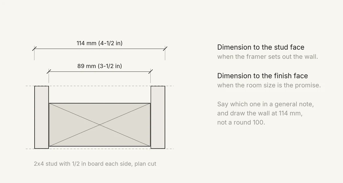
Put the rule in a note, such as "Dimensions to structural face unless noted". Then mark every string that breaks the rule. The guide to floor plan dimensions covers how to build and place the strings.
Mixing faces without a note moves rooms. A room 3,600 mm between the centrelines of two 114 mm partitions is 3,486 mm between finishes. A schedule taken from centrelines overstates that room by a full wall thickness.
Measure room areas to finishes before you compare them with the brief. The guide to space planning and room areas against the brief covers that comparison in detail.
Set one alignment rule per wall type
Decide which face of each wall type sits on the line you draw, then keep that rule for the whole job. A centred wall splits its thickness either side of the line. A wall aligned to one face keeps that face on the line, and all the thickness goes the other way.
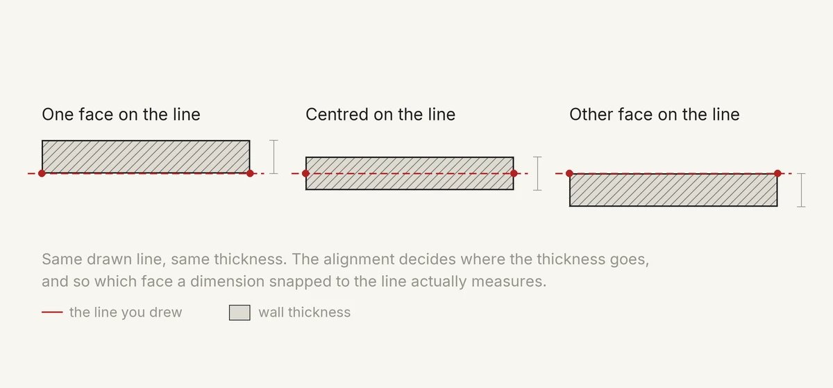
Draw external walls along the face your setting-out runs to. Draw partitions along the finish face of the room you are sizing. When the board thickness changes later, an aligned face stays put and only the far face moves. A centred wall moves both faces by half the change, so both rooms shift.
In Synaps, the alignment control sets a wall Left, Center or Right of the line you drew. A run drawn along the finish line keeps that face where you put it.
Set up wall build-ups in Synaps
Synaps publishes this article. Synaps is browser-based architectural design and drafting software, and each wall carries its thickness and its build-up in layers.
The job is the fit-out plan from the opening: stud partitions at their real build-up instead of a round 100 mm. Use the same thickness, layers and alignment for every wall of a type.
- Draw the partition run with the wall tool. Segments in one run join at the corners. Enter L for length and A for angle in the tool panel when you have the figures.
- Select the wall to open its properties. For a single-layer wall, set its thickness to the total from your wall list.
- Set the alignment to Left, Center or Right, following the rule you chose for partitions.
- For a layered wall, click the core layer row and set it to the stud width, 89 mm. Click Add left and Add right to put a board layer on each face. Click each board row to set it to 12.7 mm, with its fill and stroke. The three layers sum to the 114 mm in your wall list. A wall holds up to eight layers.
- Choose Room from command search, then click inside each closed wall loop. The room stays tied to its walls and re-measures itself when a wall's thickness or position changes.
- Place dimensions with Chained placement, snapping each point to the wall geometry. Add your dimension-face note as an annotation.
- Export the paper as PDF for the client, or as DXF for a consultant who works in CAD.
Frequently asked questions
How thick are exterior walls?
Build an exterior wall from its layers, the same way as a partition. A 2x6 frame with 1/2 in board inside is 5-1/2 + 1/2 = 6 in (152 mm). That is before sheathing, cladding and any insulation outside the frame. In England, a Section 2C cavity wall starts from the leaf and cavity minimums in the masonry section. Take every other layer from its data sheet and add it to the sum.
Should the plan show each layer of the wall?
Show layers where the scale can carry them. At 1:100, a 114 mm partition is 1.14 mm on paper, and each 12.7 mm board is about 0.13 mm. Draw the outline and fill the cut at that scale. At 1:50 or larger, show the board as its own layer. The guide to architectural drawing scales covers which drawing suits which scale.
How do I draw an existing wall when I can't see its build-up?
Measure the overall thickness where the wall is open, such as at a doorway, and draw that total as a single layer. Note that the build-up is unknown, so nobody reads layers into it. Replace it with real layers once a survey opens the wall. The guide to as-built drawings covers measuring existing walls.
Does a thicker wall on the plan mean a stronger wall?
No. Thickness on the plan records what gets built, and strength comes from the engineer's design of the core. Swapping 1/2 in board for 5/8 in board each side makes a partition thicker, and that change says nothing about load. Draw the total from the build-up and the core from the engineer.
What sizes should I use for metric plasterboard and metal studs?
Use the sizes on the manufacturer's data sheet for the product you specify. Metric boards and metal studs come in their own ranges, and the US sizes in this guide are not a stand-in for them. Sum the stud width and each board the same way, then write the total into your wall list.