


A section drawing is a scaled vertical cut through a building, taken where heights change and marked on the plan. A two-storey house is on your screen in plan, the stair is drawn, and the section sheet is still empty.
Key takeaways
- Cut through the stair, every change of level and the tallest space.
- Mark each cut on the plan with a letter, a viewing direction and a sheet number.
- Chain the vertical dimensions from the foundation up, and tie every level to one datum.
- Draw cut elements heaviest, and everything beyond the cut progressively lighter.
- Trace each section along its cut line against the plan before every issue.
What a section drawing shows
A section shows what a plan cannot: floor thickness, ceiling heights, the stair in flight and the ground below. What must appear on the sheet depends on who reads it. The table below sets three kinds of reader side by side.
| Item on the sheet | Los Alamos (LANL) CAD standard | UK council guidance | Morgan Hill, California |
|---|---|---|---|
| Cut construction | All sectioned building systems and large components | Cross sections through buildings (all three councils) | Building framework from ground level to peak, with framing and insulation |
| Beyond the cut | Background elevation features of the interior | - | - |
| Material symbols | Section symbols for primary systems materials | - | - |
| Foundations | Foundation to floor dimensions | Foundation details where ground levels change (Bradford) | Foundation and crawl space height |
| Floors | Floor to floor dimensions and floor system thickness | Finished floor levels (Oxford, North Somerset), and where ground levels change (Bradford) | Ceiling heights |
| Roof and bearing | Primary bearing heights | Ridge levels (Oxford, North Somerset), eaves details where levels change (Bradford) | Attic space height |
| Ground | - | Existing and proposed levels where levels change (Bradford), cut and fill is significant (Oxford, North Somerset) or slopes exceed 1 in 20 (North Somerset) | Finish grade |
| Datum | - | Fixed datum off site where levels change (Bradford). On level drawings, usually Above Ordnance Datum (North Somerset) | - |
| Neighbours and land | - | Buildings within and adjacent to the site, and sections through land (Oxford, North Somerset). Adjoining buildings where levels change (Bradford) | Grading cross sections at dwelling unit and property lines |
| Cut location | Building section cut symbols on plans and elevations | A plan showing the points the sections run between, with north (Oxford, North Somerset) | - |
| Scale through buildings | Minimum 1/4 inch to the foot, preferably 3/8 inch | 1:50 or 1:100 (Bradford, and normally in North Somerset) | - |
| Scale through land | - | Normally 1:200 or 1:500 (North Somerset) | - |
| Notes and references | Notations, symbols, call outs and references to enlarged details | - | - |
A dash means the source is silent on that row.
The LANL column is the building section list in the Los Alamos National Laboratory CAD standard, Section 300. That standard belongs to one organisation, so treat it as a worked example.
The UK column starts with the drawing standards of Oxford City Council, dated August 2021.
Bradford's entries come from the local validation requirements of Bradford Council for site sections and levels.
The other UK entries come from the North Somerset Council drawing standard on the same subject.
The last column is the 2023 plan content checklist of Morgan Hill, California, one US city's list for houses.
Building, wall and site sections
Three kinds of section answer three different questions, so decide first which question the sheet must answer.
A building section cuts through the whole building and shows how the floors, stair and roof stack up. A wall section cuts one external wall from footing to roof at a larger scale. Use it for the junctions a building section is too small to show: footing, sill, head and eaves. For the wall build-up itself, see our guide to standard wall thickness.
A site section cuts through the land and shows how the building sits on the ground. North Somerset Council separates building and land sections by scale, with sections through land "normally at a scale of 1:200 or 1:500". Draw the site section from the same survey as the site plan, so the levels agree.
Where to cut
Place the cut where the heights change, because a section through a plain room tells the reader very little.
Cut through the stair first, since that view proves the rise, the headroom and the landing levels. The Planning Portal asks for "A cut through of the key new parts of the development such as stairs".
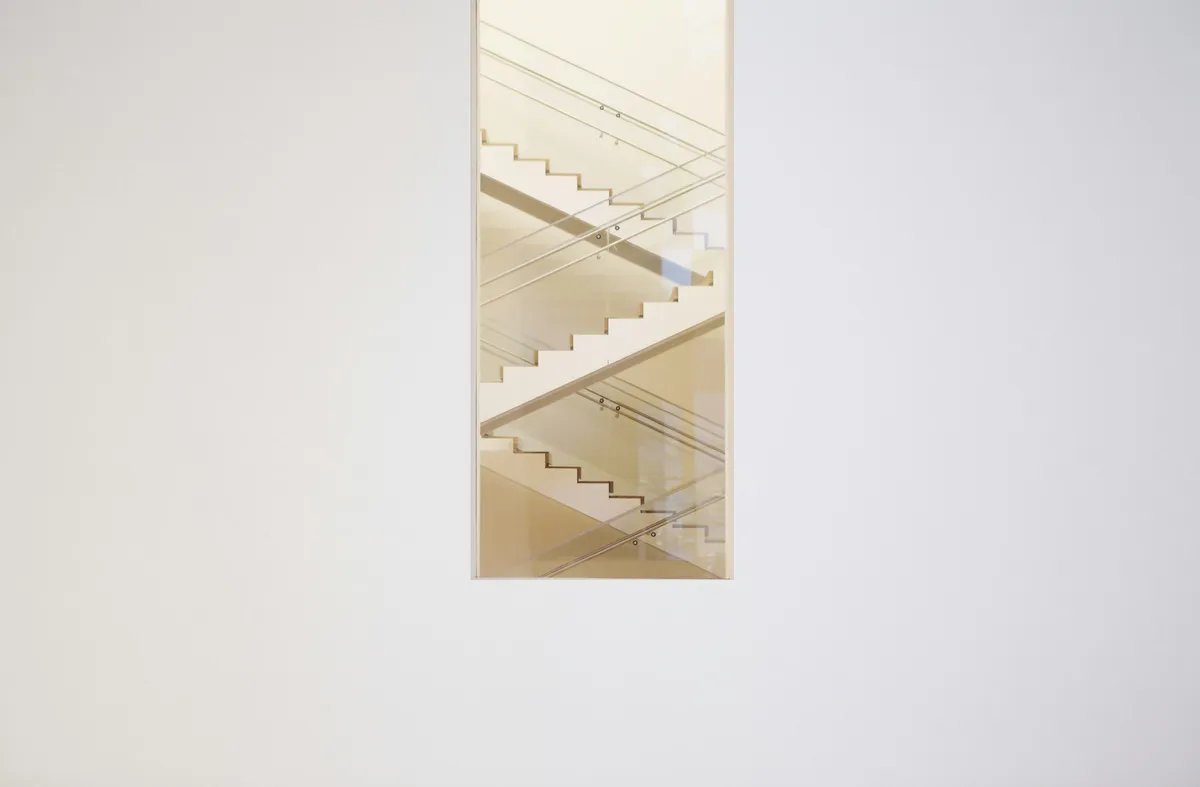
Then cut through every change of level: a split floor, a sunken room, a step in the roof. Take the tallest space next, such as a double-height hall or a room open to the rafters.
Keep the cut line straight where you can. Jog it only to catch a stair or a void, and make each jog at right angles through open floor. Pass through windows and doors rather than along a wall, so openings show their sill and head heights.
The Synaps section tool takes two points and a viewing side, and the section updates with every model change.
Mark the section on the plan
A section the reader cannot locate on the plan is hard to trust, so draw the marker with care.
The Los Alamos National Laboratory CAD standard, Section 200, identifies sections by letters and details by numbers. The same section says, "Do not duplicate letter or numbers on either the Sections or Detail sheets." The standard starts section letters at A and runs them from the upper left of the sheet to the lower right.
Draw the marker as a cut line with a head at each end. Put the letter in the top half of the head and the sheet number in the bottom half. Point each arrow in the viewing direction, because a cut looking east and one looking west are different drawings.
Oxford City Council says section drawings should "Be accompanied by a plan showing the points between which the cross sections have been taken, which should also indicate the direction of north".
North Somerset Council uses the same wording in its drawing standard. Put a north point on the key plan and a marker at both ends of the cut.
Repeat the marker on the elevations. Our elevation drawing guide covers the rest of that sheet.
Set the scale
Draw the building section at the plan's scale or one step larger, so heights read clearly.
The Los Alamos National Laboratory CAD standard, Section 300, sets a minimum of 1/4" = 1'-0" for building sections, preferably 3/8".
The Section 200 scale table of the same manual lists five scales for sections, from 1/8" = 1'-0" to 1" = 1'-0".
The two parts of the manual look contradictory, because the table's smallest scale is below the building section minimum. Read the table as the range for all disciplines and the minimum as the floor for architectural building sections.
The UK guidance quoted here sets its scales in metric ratios. Bradford Council says section drawings "should be drawn at a scale of 1:50 or 1:100".
The chart converts the LANL section scales to ratios, at 12 inches to the foot, beside the two metric scales.
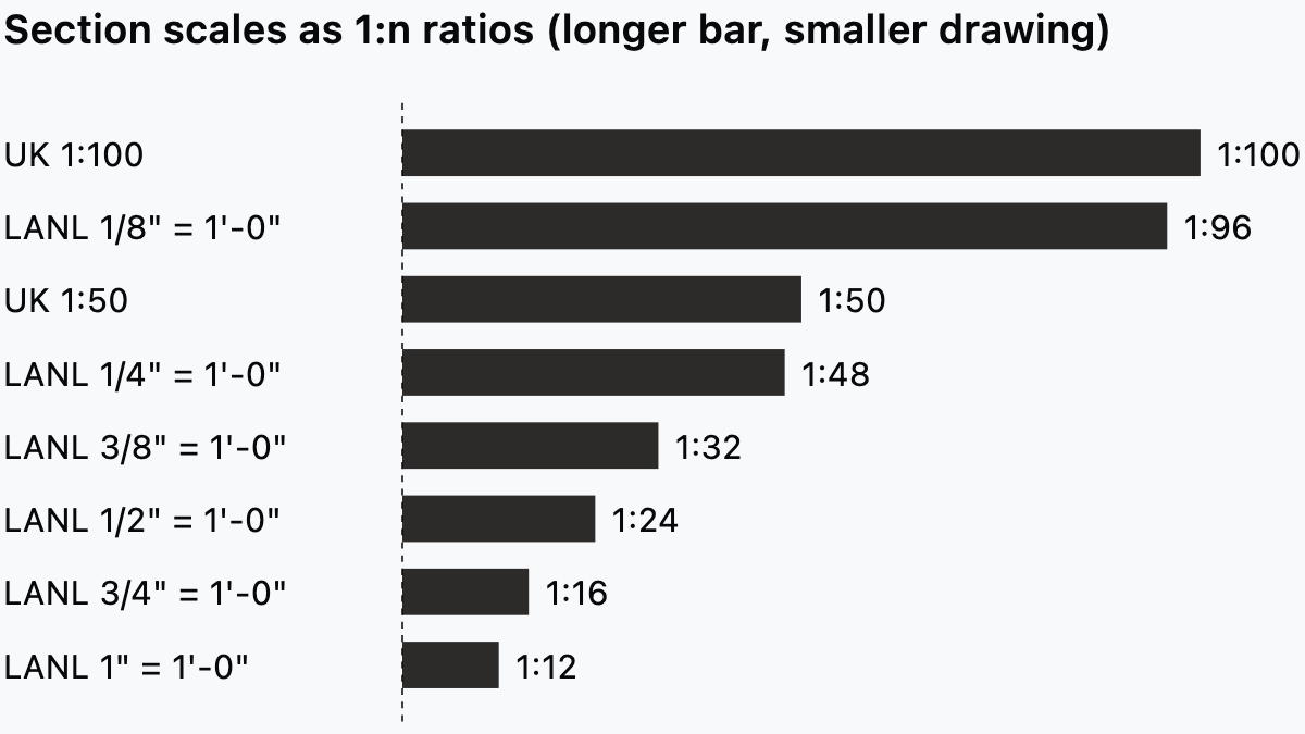
Each metric scale has an imperial neighbour a little larger, 1:96 beside 1:100 and 1:48 beside 1:50. Four LANL scales are larger still.
Our guide to architectural drawing scales covers the rest of the set.
A Synaps paper takes an ISO size and a scale such as 1:50, and exports as PDF or DXF.
Vertical dimensions and levels
Dimension a section vertically and leave the horizontal chains to the plan. Our guide to floor plan dimensions covers those chains.
The Los Alamos National Laboratory CAD standard opens its vertical list with "Foundation to floor dimensions" and "Floor to floor dimensions". Next come "Floor system thickness" and "Primary bearing heights".
Dimension the section in this order:
- Set the datum and mark the existing and finished ground levels against it.
- Dimension from the top of the foundation to the lowest finished floor.
- Chain the floor to floor heights up one side of the section.
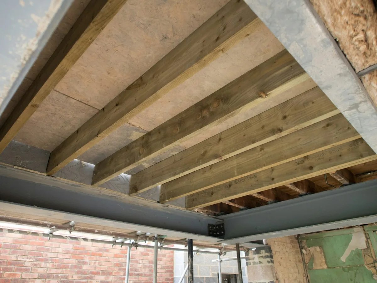
- Show each floor build-up, so ceiling height and storey height both read.
- Add the bearing height of the roof structure, then the ridge or parapet level.
- Close the chain with one overall height, and confirm the parts add up to it.
- Dimension the heights no other sheet carries, such as stair headroom and the clear height under a beam.
A level needs a datum to mean anything. Where ground levels change, Bradford Council asks for finished floor levels "with levels related to a fixed datum point off site".
For level drawings, North Somerset Council asks for a fixed and identifiable datum, usually Above Ordnance Datum (AOD). Write each level as a spot height against that datum, and use the same datum on the site plan.
In Synaps, each floor's height feeds the sections, and stairs know those floor heights and show in the section.
Cut lines, hatching and what sits beyond
Line weight tells the reader what the cut passes through and what merely sits behind it.
Draw every cut element with the heaviest line on the sheet: walls, floors, roof and foundations. Give the ground line the same weight and run it well past the building. Use a medium line for surfaces just beyond the cut, and a fine line for anything further back.
The Los Alamos National Laboratory CAD standard asks for "All background architectural elevation features shown (interior elements)." So the doors, windows, balustrade and joinery beyond the cut appear in elevation, drawn light.
Fill the cut with poche or hatching, and let the scale decide which. At 1:100, a solid fill reads better than material hatching. At 1:50 and larger, hatch each material and show the layers of floor and wall.
In Synaps, convert the section to polylines when the design is settled, then add dimensions, text and leader callouts.
Keep the section in step with the plan
Sections drift from plans more easily than elevations do, because the cut line itself can move. Someone shifts a stair or a wall on the plan, and the section still shows last week's building.
Before each issue, run these checks in whatever tool draws the set:
- Confirm each marker on the plan matches a titled view, with the same letter and viewing direction.
- Walk along the cut line on the plan and list every wall, opening and stair it crosses.
- Find each of those elements in the section, in the same order and at the same distance.
- Compare each wall thickness in the section with the plan, element by element.
- Count the stair risers in plan and in section, and confirm the landing levels match the floors.
- Compare the floor levels and the roof line with the elevations.
- Record the revision on the plan and the section together whenever a change touches the cut line.
Sections for a planning or permit submission
Whether a submission needs a section depends on the authority and the site, so read the local list first.
The Planning Portal says a cross-section "is needed when there is a change in ground levels such as creating steps or filling, or on sites which lie on large slopes."
Bradford Council applies its rule to "All applications where new building work is proposed".
Those two sources look contradictory, since one ties the section to slopes and the other to any new building. Read the Planning Portal as the general case and the local list as the rule for your site.

Oxford City Council says that in householder development "the levels may be evidenced from floor plans and elevations". On sloping sites, the same guidance says "it will be necessary to show how proposals relate to existing ground levels".
On a stepped street, draw the neighbours on both sides at their true levels, so ridge heights can be compared.
A building permit checklist reads the section differently. Morgan Hill, California, asks for a "Cross section view through the building framework from ground level to peak showing finish grade, foundation, framing elements, insulation, ceiling heights, crawl space height and attic space height."
That reader checks how the house is built, so keep the framing and insulation legible at the chosen scale.
Section drawings in Synaps
In this workflow, Synaps takes each section from the plan's own model, and you dimension and annotate it.
- Draw the walls and set their thickness, then set the height of each floor.
- Add the stairs and the roof, which both show in the section.
- Open the section tool, click two points across the plan and choose the viewing side.
- When the design is settled, convert the section to polylines. Add vertical and chained dimensions with D, text with T and leader callouts with Shift+D.
- Create a paper at 1:50 or 1:100 on an ISO size, then export the sheet as PDF or DXF.
Dimensions, text and leader callouts stay where you place them. The view titles and level marks on the sheet are yours to add.
If your next house needs two sections cut from one plan, try Synaps for free and cut the first one.
FAQ
What is the difference between a cross section and a longitudinal section?
A cross section cuts across the short dimension of the building, and a longitudinal section cuts along the long one. On a gable roof with the ridge along the length, the cross section shows the pitch. The longitudinal section shows that same ridge as one level line above the rooms.
How many sections does a small building need?
Two is the working minimum for a house: one across and one along, with one of them through the stair. Add a section for each change of level or roof form that the first two miss. Bradford Council asks for "a cross section(s) through the proposed building(s)". So let the building decide how many the sheet carries.
What is the difference between a section and an elevation?
A section cuts through the building, and an elevation looks at one face from outside without cutting. The elevation gives the heights you can see, and the section gives ceiling heights, floor thickness and stair headroom. Our elevation drawing guide sets out how to draw each face.