An elevation drawing is a flat, scaled view of one building face, projected straight from the plan. It shows heights, openings, materials and the ground line. Picture the ground floor plan of a rear extension open on your screen, with four empty elevation frames waiting on an A1 sheet beside it.
Key takeaways
- Project each elevation from the plan and draw it at the plan's scale, so widths and openings come from one drawing.
- Give each elevation a letter and a direction, and put a matching marker on the plan.
- Dimension heights from the ground up: grade, each floor level, eaves or parapet, then the overall height.
- Compare every opening between plan and elevation, wall by wall, after each revision.
- For a planning application, read your council's list first, then draw each face it asks for in full, existing and proposed.
What an elevation drawing shows
What goes on an elevation depends on who reads the sheet. The Los Alamos National Laboratory CAD standard lists elevation content under a heading that opens "Including but not limited to the following:". The LANL column below is a selection from that list, plus its scale rule and the naming rule from its Section 200.
The UK column draws on planning guidance from North Northamptonshire Council, Oxford City Council and Northumberland County Council. The last column comes from El Monte, California, one US city.
| Item on the sheet | LANL CAD standard | UK council examples | El Monte |
|---|---|---|---|
| Ground line | Finish grade lines | - | Existing and finished grade on all elevations |
| Foundations | Extents as a hidden line below grade | - | - |
| Doors and windows | Drawn to scale with swings and symbols | Positions identical on elevations and floor plans | Type and colour noted, as with materials |
| Floor levels | Each floor and roof bearing level identified | - | Heights above average natural grade for all floors |
| Roof height | Finished first floor to top of roof or parapet | - | Heights above average natural grade for eaves and ridges |
| Window sills | Height of each sill | - | - |
| Overall length | Dimensioned | - | - |
| Materials and finishes | Materials and types, finish changes, copings | - | Type, colour and other attributes noted |
| Section marks | Building section cut symbols | - | - |
| Scale | Same as the plans, preferably | Normally 1:50 or 1:100, with a scale bar | Bar scale on all drawings |
| Faces to draw | - | Every face affected, blank walls included (North Northamptonshire), or every elevation (Oxford) | - |
| Existing and proposed | - | Separate sets in most cases | - |
| Context | - | Outlines of close buildings and the property boundary | - |
| Labels | Exterior elevations by plan direction | Compass orientation of each face | Site orientation and direction |
A dash means that source is silent on the row. Each source writes for its own readers, so follow your own authority's wording.
Line weight gives a flat elevation its depth. Draw the ground line heaviest, then the outline of the building. Use lighter lines for planes set further back, such as recessed bays and window reveals. Keep hatching or tone to changes of material, so the face stays easy to read.
Exterior and interior elevations
Draw one elevation for each direction the building faces. On an L-shaped plan, the south elevation shows both south-facing walls in one view. Add a separate elevation only for a face hidden from every main view, such as a courtyard or a recessed entrance.
Draw the blank faces as well. North Northamptonshire asks for "all faces of the building affected by the works, including blank walls", while Oxford asks for every elevation.
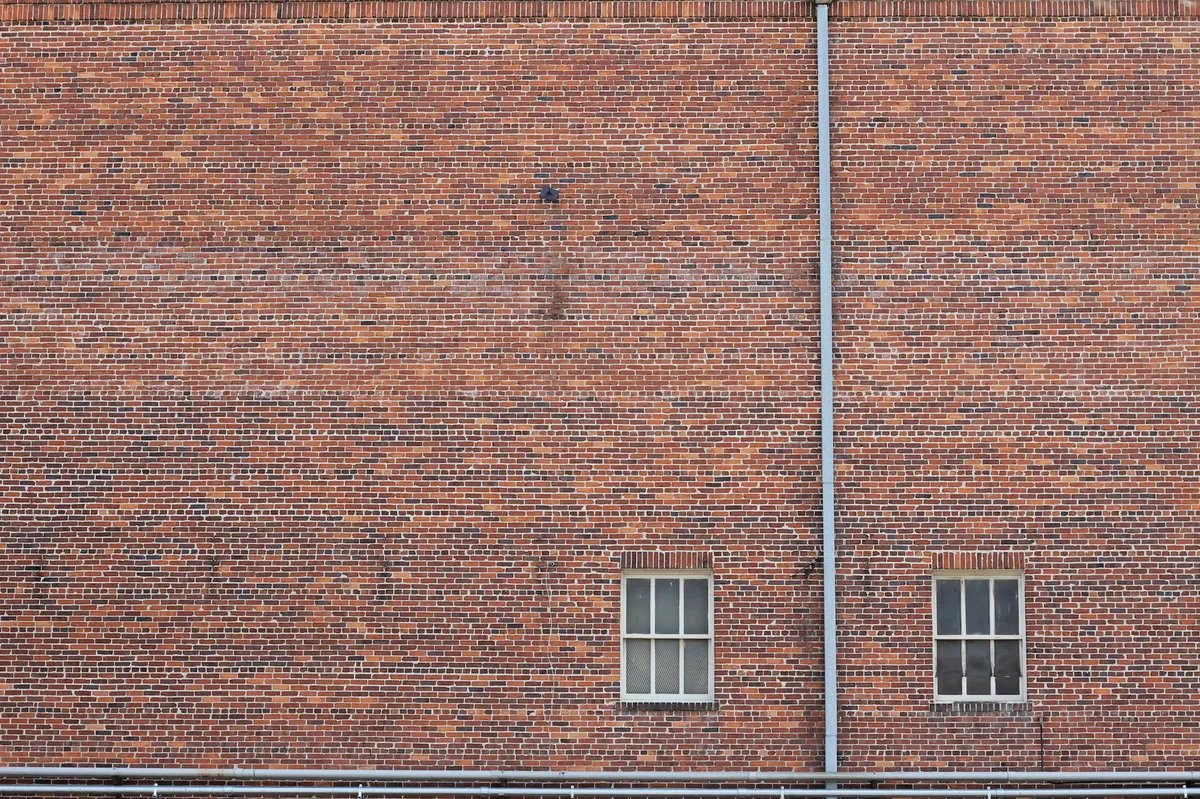
Set up every exterior elevation the same way. Take the walls that face that direction from the plan, and project their ends and every opening edge down to a ground line. Then build the heights up from that line, so the elevation inherits its widths from the plan.
The Synaps elevation tool creates an elevation when you click a highlighted wall, and it updates with every model change.
Interior elevations earn their place where a wall carries work the plan cannot show, such as a kitchen run, a bathroom, joinery or a stair. Each one sets out a single wall: worktop and splashback heights, sockets, switches, joinery fronts and tiling extents. Draw it larger than the plan, for example at 1:20 or 1:25 against a 1:50 plan. Key it from the room plan with a marker pointing at the wall it shows.
Name each elevation and reference it from the plan
The Los Alamos National Laboratory CAD standard, Section 200, says, "Reference exterior elevations by the plan direction (i.e., North, South, East, and West)."
The direction rule above covers exterior faces only. For references, the same LANL section says, "Identify sections and elevations by LETTERS, and details by NUMBERS." LANL letters views by their position on the sheet, from "A" at the upper left to the lower right. Many studios letter interior walls A to D clockwise from the door instead. Pick one order and keep it across the set.
The councils quoted here name faces by the compass. North Northamptonshire Council says, "Each elevation should be labelled to show its compass orientation."
Oxford City Council asks applicants to "state the direction in which each elevation faces, eg. Rear (south)."
El Monte asks that each elevation be labelled "by both site orientation (front, rear, left side and right side) and direction (North, South, East and West)." A label such as Rear (south) meets Oxford and El Monte at once.
LANL names faces by plan direction, while the councils ask for compass orientation. If you read LANL's plan direction as plan north, a plan turned away from true north gives one face two names. For a planning submission, name faces by true compass direction and show the north point on the plan.
Then tie each elevation to the plan. Place a marker outside each face with its letter and the number of the sheet the elevation is drawn on. On the elevation sheet, title each view with the same letter, its direction and its scale.
Set the scale and the sheet
Draw the elevations at the scale of the plans. The Los Alamos National Laboratory CAD standard says, "All building elevations are preferably to be drawn in the same scale as the building plan drawings." Its Section 200 scale table lists six imperial scales for floor plans and elevations, from 1/16" = 1'-0" to 3/8" = 1'-0".
The councils quoted here name metric scales. North Northamptonshire Council says elevations "should normally be to a scale of 1:50 or 1:100."
Oxford City Council asks for "a suitable metric scale, for example 1:100 or 1:50".
Draw the plans at 1:50 or 1:100, and the elevations meet the LANL rule and the council scales together.
To compare them, convert each imperial scale to a ratio. At 1/4" = 1'-0", a quarter inch on paper stands for 12 inches on site, so 1:48. The chart sets all six beside the UK scales.
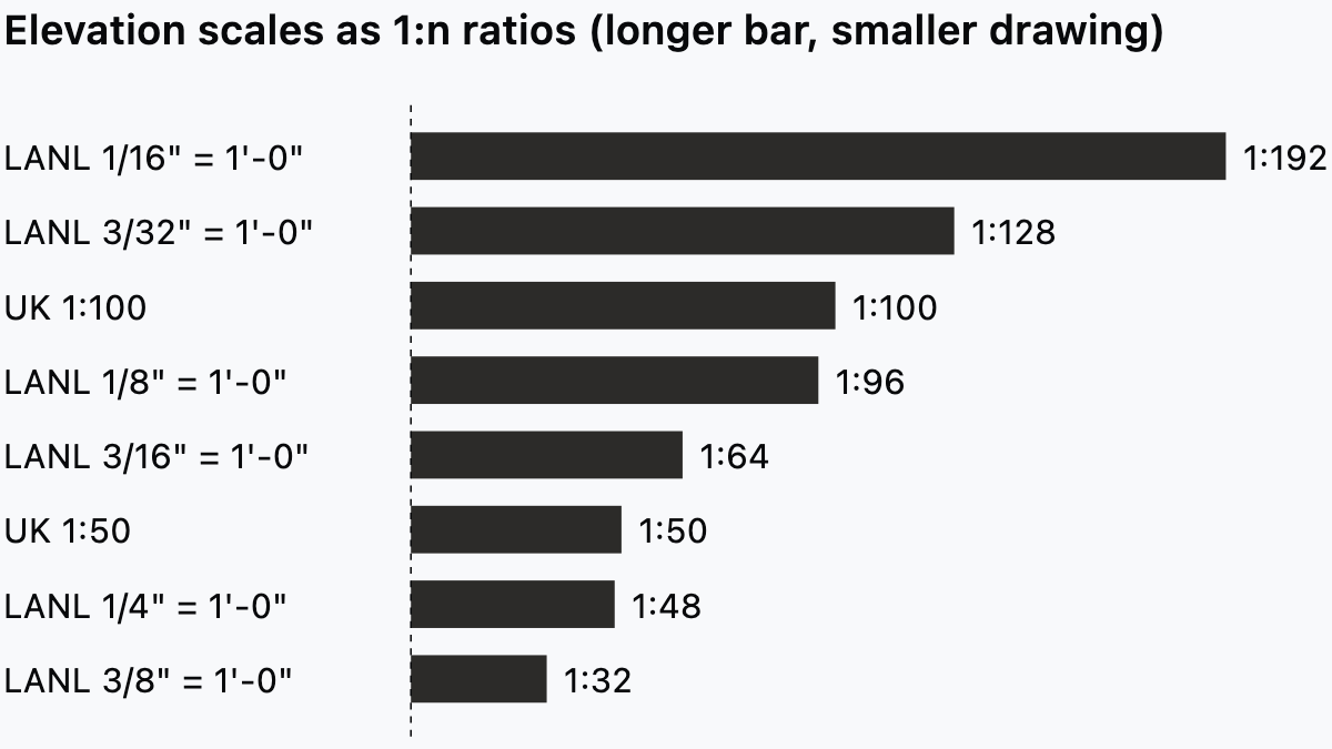
Read 1:96 as close to 1:100, and 1:48 as close to 1:50. Close is not equal, so never relabel an imperial drawing with the nearest metric ratio. Our guide to architectural drawing scales covers scale choice across the rest of the drawing set.
Then set up the sheet so the scale survives printing. North Northamptonshire Council says it "cannot accept drawings with 'do not scale' written on them", and that "An acceptable format is for the scale to be shown as 1:100 at A1 or 1:200 at A3."
So strip any "do not scale" note from the title block template you use for planning sheets. A3 is half the width and height of A1, so an A1 sheet at 1:100 prints at 1:200 on A3.
El Monte asks for "a bar scale for all drawing to preserve a scale on any reduced versions of the plans". Put the scale bar beside each view, and the paper size, drawing number and revision in the title block.
In Synaps, a paper takes an ISO size and a scale such as 1:50 or 1:100, and it exports as PDF or DXF.
Heights and levels to dimension
Dimension heights in a fixed order from the ground up. The Los Alamos National Laboratory CAD standard says, "Each floor elevation and roof bearing elevation shall be identified as well as any changes within a floor line with a 0.050 broken line."
The same LANL list asks for heights such as "Grade to first floor", "Floor to floor elevations" and "Overall finished first floor to top of roof or roof parapet or mechanical parapet", plus "Height elevations of window sills".
El Monte asks applicants to "Show any heights above average natural grade for all floors, eaves and ridges." That city measures from average natural grade, so take the datum your authority names before you set the first level.
Dimension the face in this order:
- Draw the ground line, with existing and finished grade where they differ.
- Mark the finished floor level of each storey on a broken line across the face.
- Chain the floor to floor heights on one side of the face.
- Add the eaves, parapet or roof bearing level, then the ridge.
- Run the overall height outside the chain, so the chain adds up to it.
- Give the sill and head heights of each window type in a second chain.
The chain logic matches the one on a plan, set out in our guide to floor plan dimensions.
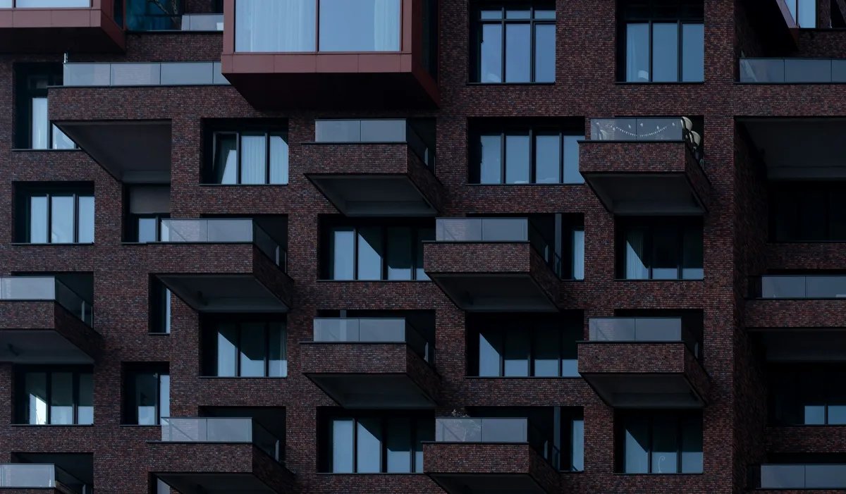
In Synaps, each floor's height feeds the sections, elevations and 3D, and flat, hip, gable and mono-pitch roofs show in the elevation too.
Materials, openings and notes
The Los Alamos National Laboratory CAD standard asks for "Materials and types" and for features such as "finish changes, architectural finish features like inset stucco bands or tile, parapet coping exterior stairs (below grade shown as hidden lines) or free standing entry canopies."
El Monte asks applicants to "Provide detailed notations for all materials doors, windows, siding, etc., listing their type, color and other attributes."
Set the notes outside the face, with a leader to each material. Use the words of the specification, so the note and the schedule never disagree.
For openings, the LANL list asks for "All attributes of building elevations drawn to scale with window and doors having swings identified." Show the opening lights of each window, and take each door's hinge side from the plan, using the conventions in our guide to door swing.
In Synaps, convert the elevation to polylines when the facade is settled, then add a leader callout for each material.
Keep the elevation in step with the plan
A plan and its elevations describe the same openings, so any difference between them is an error in the set. North Northamptonshire Council says, "The positions of doors and windows must be identical on the elevations and floor plans."
Northumberland County Council's example sheet puts the same point as a checklist line: "All window and door openings are shown (and you have checked the positions/sizes match the floor plans)."
Drift starts when the elevation is separate linework, and a window moved on the plan stays put on the face. In Synaps, doors and windows sit on their walls with a set width, height and sill, and the elevation follows every model change.
Before each issue, run this check on every face:
- Count the openings on each wall in plan, then on the matching elevation.
- Measure each opening from the nearest corner in both drawings.
- Compare each opening's width in plan with its width on the face.
- Compare sill and head heights on the face with the window schedule.
- Check the overall length of each face against the wall lengths on the plan, returns included.
- Check the floor levels and the roof line against the sections.
- Revise the elevations whenever a plan change moves an opening, and note it in both revision boxes.
Elevations for a UK planning application
Requirements differ from one council to the next, so read your own authority's validation list before you set up the sheet.
North Northamptonshire Council asks for drawings that "show the existing and proposed elevations and floor plans of each storey to be built or altered", and says, "Partial elevations and floor plans are not acceptable as your proposal needs to be considered in relation to the whole of the existing building".
Oxford City Council asks you to "Show outline elevations of other buildings that are close to the development" and to "Show the property boundary".
Draw the existing set first, then copy it and make the changes, so both sets share one ground line and one scale.
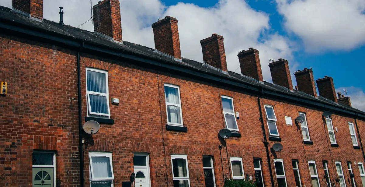
On a terrace or a semi-detached house, draw the neighbour's face in outline next to yours. Mark the line where your elevation meets the next building, and show the boundary where it crosses the face.
Elevation drawings in Synaps
Synaps is the company behind this blog and makes the drafting software described here. In this workflow, Synaps takes each elevation from the walls of one plan, and you dimension, annotate and place it on a sheet.
- Draw the walls, then place each door and window on its wall and set its Width, Height and, for a window, Sill.
- Set the height of each floor in the floor switcher, so the levels carry into sections, elevations and 3D.
- Open the elevation tool and click the highlighted wall of the face you need.
- When the facade is settled, convert the elevation to polylines. Add vertical and chained dimensions with D, text with T and leader callouts with Shift+D.
- Create a paper at 1:50 or 1:100 on an ISO size, place the elevation on it and export the sheet as PDF or DXF.
Synaps does not name the elevations or add levels, materials or hatching to them by itself. The view titles, level marks and material notes on the sheet are yours to add.
If your next extension needs four elevations drawn from one plan, try Synaps for free and set up the first elevation from its walls.
FAQ
What is the difference between an elevation and a section?
An elevation looks straight at a face without cutting through it, and a section cuts through the building and looks at the cut. The section shows floor build-ups, ceiling voids, stair flights and true wall thickness. The LANL sheet order files elevations as sheet type 2 and sections as type 3.
How many elevations does a house need?
A plain rectangular house needs four, one for each direction, and a courtyard or a hidden return adds its own view. Oxford City Council says that "In most cases, two separate sets of elevation drawings will be required", existing and proposed. A four-sided house altered on every face then needs eight.
Which scale should an elevation drawing use?
Use the scale of the plans, which in UK planning work usually means 1:100 for a whole house or 1:50 for an extension.