

Stairs on a floor plan are tread lines, an arrow showing the direction of travel, a riser count and, on the lower floor, a cut line. You have drawn the ground floor of a two-storey house, the upper plan is open, and the stair is still a blank rectangle.
Count the risers from the floor-to-floor height before you draw a single tread. The count sets the run, and the run sets the hall, the landing and the opening above.
Key takeaways
- Divide the floor-to-floor height by a trial rise, round to whole risers, then divide again.
- A straight flight that lands on the upper floor has one tread fewer than risers.
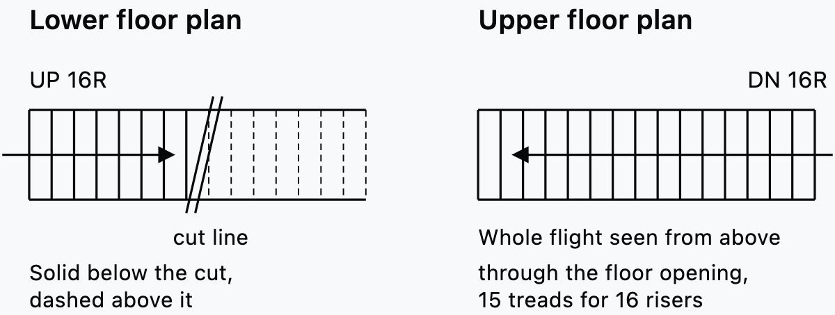
- The lower plan breaks the flight at a cut line and dashes the treads above it. The upper plan shows it whole.
- Label each flight with its count, rise and going, such as "16R at 175, 15G at 250".
- Run the plan-side checks before the section is cut, starting with the riser count on both plans.
What a stair looks like on a floor plan
A stair appears on two floor plans, and the two drawings differ. The lower plan is cut about 1.2 m, or 4 ft, above the floor, so the flight is broken partway up. The upper plan looks down through the floor opening and shows the whole flight.
Four marks carry the information on both plans:
- Tread lines, one for each riser, drawn across the width of the flight.
- An arrow along the centre of the flight, showing the direction of travel.
- The word UP or DN at the tail of the arrow, with the riser count.
- Handrails and guards, drawn as thin lines along the sides.
The lower plan adds a fifth mark, the cut line, drawn as a diagonal break across the flight. The diagram shows one 16-riser stair on both plans.
The stair is one symbol among many on the sheet. Our guide to floor plan symbols covers the doors, windows and fixtures around it.
Size the stair before you draw it
The riser count comes first, because every other stair dimension follows from it. Take the floor-to-floor height, finished floor to finished floor, from the section or the level schedule.
Two documents serve as reference points in this guide. The first is the 2021 International Residential Code (IRC), section R311.7, in the Stairway Manufacturers Association's illustrated reproduction. That code applies to US one- and two-family dwellings where the edition is adopted.
The second is Approved Document K, 2013 edition, which is guidance for England. The code adopted where the building stands decides, and local amendments apply.
Work through the count in four steps:
- Divide the floor-to-floor height by a trial rise.
- Round to a whole number of risers, then divide the height by that number.
- Subtract one to get the treads, because the top riser lands on the upper floor.
- Multiply the tread count by the going to get the run.
A metric example starts with 2,800 mm from floor to floor. Sixteen risers give 2,800 / 16 = 175 mm of rise. Fifteen goings at 250 mm give a run of 3,750 mm.
Check that stair against the guidance for a private stair, meaning a stair for one dwelling. Twice the rise plus the going is 350 + 250 = 600 mm, inside the normal range of 550 to 700 mm. The pitch is 35 degrees, under the 42 degree maximum for a private stair.
Against the IRC, the 175 mm rise is under 196 mm. The 250 mm going falls 4 mm short of the 10 in (254 mm) minimum tread depth. A 254 mm going clears it, with a run of 3,810 mm.
Fewer risers shorten the run and steepen the stair. Fourteen risers give a 200 mm rise, a 3,250 mm run and a pitch of 38.7 degrees. That rise sits inside the private stair range and above the IRC maximum of 196 mm.
An imperial example starts with 9 ft 4 in, or 112 in. The IRC sets a maximum riser height of 7 3/4 in, and 112 / 7.75 = 14.45. The fewest is therefore fifteen risers. Each riser is 112 / 15 = 7.47 in, about 7 15/32 in. Fourteen treads at the 10 in minimum depth give a run of 140 in, or 11 ft 8 in.
Against the private stair figures, that is a 190 mm rise and a 254 mm going, both inside the ranges. Twice the rise plus the going is 633 mm, inside the normal range. The pitch is about 36.7 degrees, under the 42 degree maximum.
With stairs in Synaps, the height and the tread and riser minimum and maximum values decide how many steps fit along the run.
Rise and going limits in the US and England
The two documents set their limits in different ways, so read them side by side. The IRC gives one set of figures for stairs in one- and two-family dwellings.
Approved Document K gives three sets in its Table 1.1, one for each type of stair.
| Figure | 2021 IRC, one- and two-family dwelling | Approved Document K, private stair | Approved Document K, utility stair | Approved Document K, general access stair |
|---|---|---|---|---|
| Maximum rise per step | 7 3/4 in (196 mm) | 220 mm | 190 mm | 170 mm |
| Minimum rise per step | - | 150 mm | 150 mm | 150 mm |
| Going or tread depth | 10 in (254 mm) minimum | 220 to 300 mm | 250 to 400 mm | 250 to 400 mm |
| Twice the rise plus the going, normal range | - | 550 to 700 mm | 550 to 700 mm | 550 to 700 mm |
| Maximum pitch | - | 42 degrees | - | - |
| Longest flight | 12 ft 7 in (3,835 mm) of rise | - | 16 risers | 12 risers, 16 by exception |
A dash means the sections named in this guide give no figure for that row. In every building, Approved Document K also asks for a change of direction where consecutive flights hold more than 36 risers.
The chart sets the two worked rises, 175 mm and 190 mm, against each maximum.
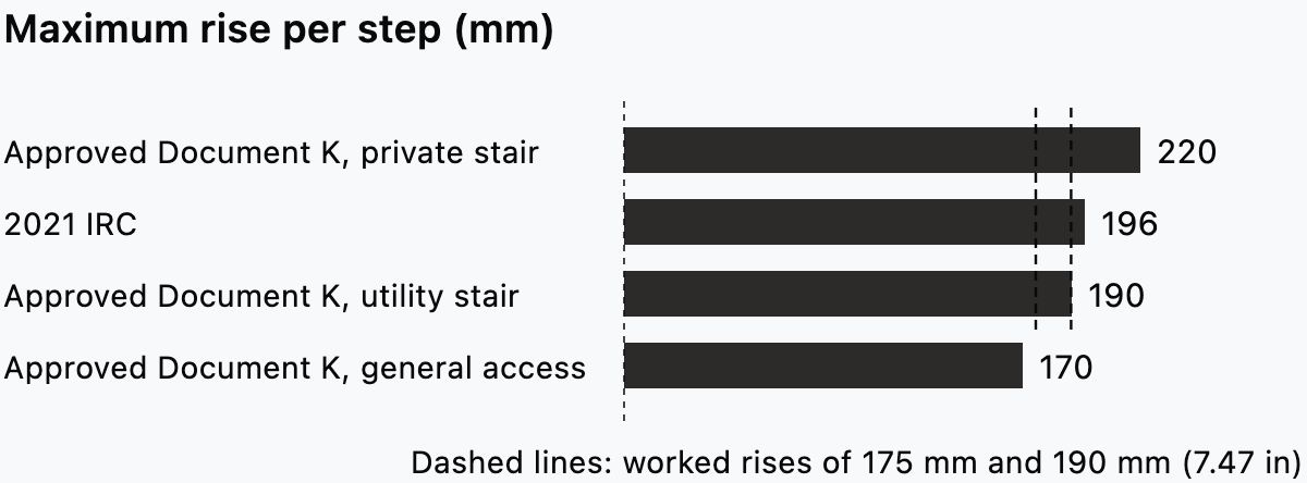
A private stair in England may rise more per step than a stair under the IRC. The tread rules differ in kind as well. One document sets a minimum tread depth, and the other gives a range for the going.
Draw the lower floor
Start at the bottom riser and draw up to the cut.
- Place the first riser line, leaving the bottom landing clear.
- Offset one line per going until the flight is about 1.2 m, or 4 ft, above the floor.
- Draw the cut line there as a diagonal break across the flight.
- Continue the treads above the cut as dashed lines, up to the top riser.
- Draw the arrow from the lower landing along the centre of the flight, and end it near the cut.
- Write UP at the tail of the arrow, with the riser count.
- Add the handrails and the wall or string along each side.
Draw a cupboard or WC under the flight in solid lines, and keep the dashed treads over it.
In Synaps, a rectangular staircase is traced as a run by clicking along its path.
Draw the upper floor
The upper plan shows the whole flight, because no cut passes through it at this level.
Draw every tread line solid, from the top riser down to the bottom one. Draw the edge of the floor opening as a firm line around the flight. Put a guard along every open edge, and carry the handrail up to meet it.
Count the lines against the lower plan. The sixteenth riser is the edge of the upper floor.
Offices differ on the arrow. It reads UP from the bottom riser, or DN from the upper landing. One drawing set must pick one rule and use it on every sheet.
Landings, doors and headroom
A stair needs clear floor at both ends, and the plan is where that floor is claimed.
For England, Approved Document K asks for a landing at the top and bottom of every flight. The width and length are each "at least as great as the smallest width of the flight". The guidance adds that a landing "should be kept clear of permanent obstructions". The IRC sets its own landing rules, so read them in the adopted edition before fixing the plan.
In a dwelling, the same guidance lets a door swing across the landing at the bottom of a flight. That allowance holds only as shown in its Diagram 1.8. Draw every door near the stair before you fix the first riser, and see our guide to door swings for the arcs.
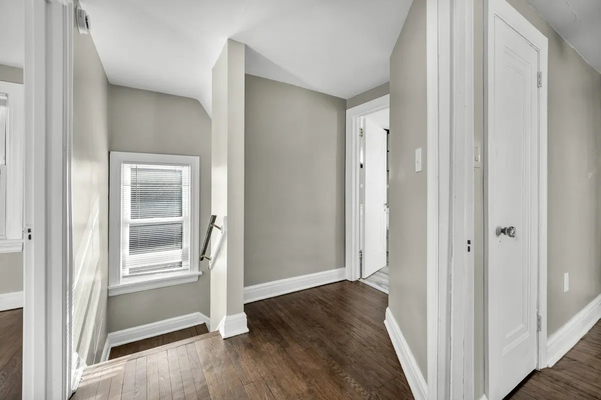
Headroom is drawn in the section, but the plan decides it. The IRC sets headroom at not less than 6 ft 8 in (2,032 mm). That height is measured vertically from the sloped line along the tread nosings.
The guidance for England gives at least 2 m over the flight and the landings, with a reduced figure for loft conversions. On the upper plan, note which tread sits under the edge of the floor opening, where headroom is tightest.
Turns: winders and spiral stairs
A turn shortens the run, and its tapered treads are measured along a line, not at an edge.
Draw winders with tread lines radiating from the inside corner or the newel. Add the walkline as a dashed curve, and run the arrow along it.
The IRC places the walkline 12 in (305 mm) from the inside of the turn. Winder treads need a depth of at least 10 in (254 mm) at that line. They also need at least 6 in (152 mm) at any point within the clear width.
Approved Document K measures tapered treads by stair width in its Diagram 1.9. On a stair under 1 m wide, the going is measured at the centre of the tread. At 1 m or more, the going is measured 270 mm from each side.
The guidance gives a 50 mm minimum tread width at the narrow end, and the same going for consecutive tapered treads. The two documents measure at different points, so draw the measuring line for your code before setting out the treads.
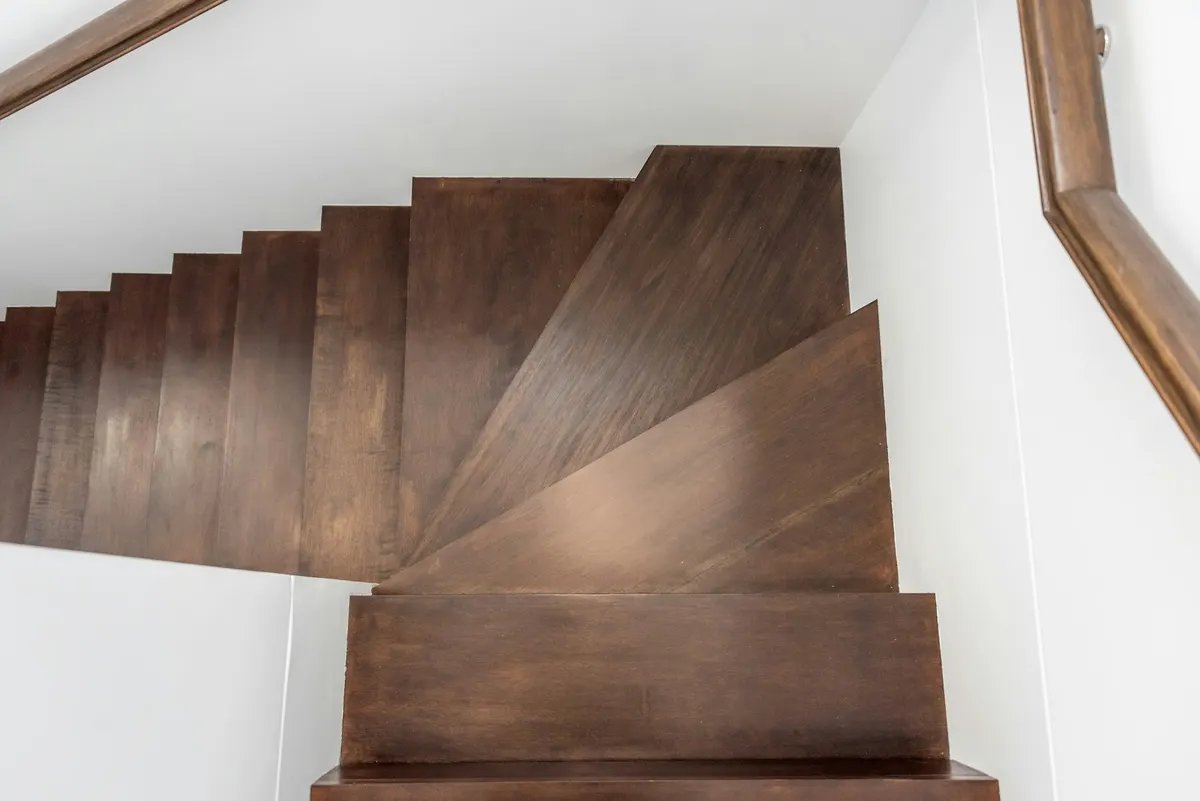
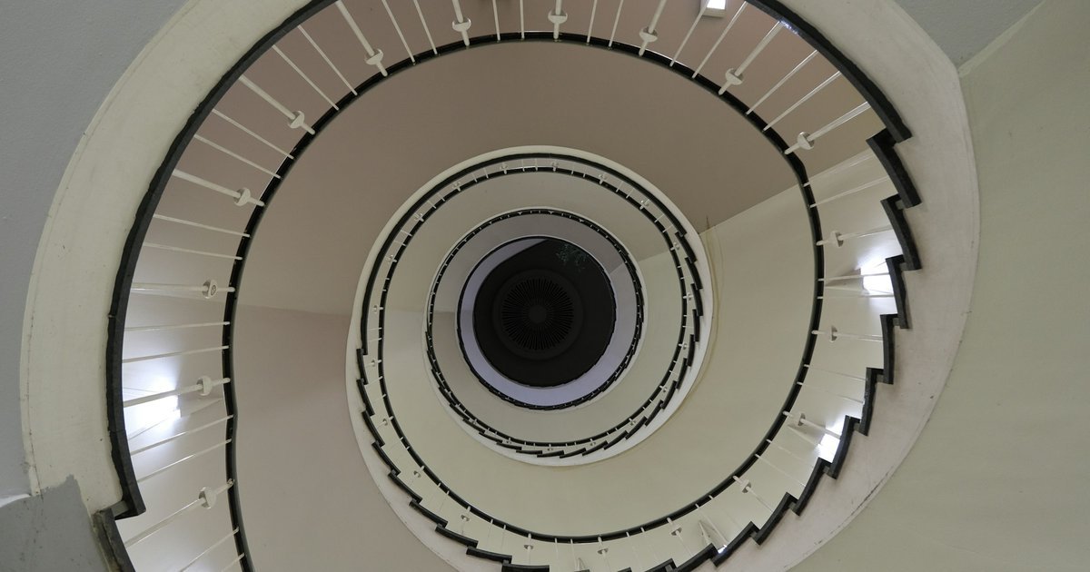
A spiral stair is drawn as a circle with a centre column and radial tread lines. Break the flight with a radial cut line on the lower plan, and curve the arrow along the walkline.
The IRC gives spiral stairways their own figures. The clear width at and below the handrails is at least 26 in (660 mm). Each tread is at least 6 3/4 in (171 mm) deep at the walkline. The rise is no more than 9 1/2 in (241 mm), and headroom is at least 6 ft 6 in (1,982 mm).
In Synaps, a spiral staircase is placed around a centre point, with radius and direction controls.
Label and dimension the stair
Write one label per flight beside the arrow: the riser count and rise, then the going count and going. The metric example reads "16R at 175, 15G at 250". The imperial one reads "15R at 7 15/32 in, 14T at 10 in", with T for treads.
Number the risers from the bottom, with 1 on the first riser, and keep the numbers the same on both plans.
Dimension four things on the plan:
- The clear width of the flight.
- The run, from the first riser to the last.
- The length and width of each landing.
- The first riser's distance from a wall face or grid line.
The IRC asks for a clear width of not less than 36 in (914 mm) above the permitted handrail height.
Approved Document K sets no general minimum width for a stair inside a dwelling. In other buildings, the guidance gives a minimum of 1,200 mm between enclosing walls, strings or upstands.
Our guide to floor plan dimensions covers the horizontal chains the stair ties into.
Check the stair before the section is cut
The plan fixes the stair's footprint, and the section proves it. Run these checks on the plans, in whatever tool draws them, before the section is cut.
- Compare the floor-to-floor height on the plans with the height used for the riser count.
- Count the risers on both plans, and confirm each flight has one tread fewer.
- Multiply the going count by the going, and measure the same run on the plan.
- Overlay the two plans, and confirm the flight sits in the same place on both.
- Confirm the top riser meets the edge of the upper floor.
- Mark the tread under the edge of the floor opening, so the section can prove the headroom there.
- Draw every door swing at both landings, and keep the landings clear.
- Confirm the arrows follow one rule and the labels agree on both plans.
Equal risers matter as much as the count. The IRC lets the greatest riser in a flight exceed the smallest by no more than 3/8 in (9.5 mm).
Then cut the section through the flight. Our guide to section drawings covers where to place that cut.
Stairs in Synaps know the floor heights and show in sections, elevations and the 3D view.
Stairs in Synaps
The job in Synaps is to place a stair that fits the floor height, then label it and put it on a sheet.
- Choose Rectangular Staircase to trace a run, or Spiral Staircase to place a stair around a centre point.
- For a rectangular stair, click to set the start of the run, then click along the intended path.
- Select the stair and set its width, height, tread and riser minimum and maximum values, and handrail options.
- Add the label as text with T and the dimensions with D.
- Put the plan on a paper at 1:50 or 1:100, then export it as PDF or DXF.
The stair tools are a rectangular run and a spiral. CAD exchange for the sheet is DXF.
If the upper floor plan is still open, try Synaps for free and draw the stair on your own plan.
FAQ
How many treads does a stair with 16 risers have?
Fifteen, when one straight flight lands on the upper floor. Split the same stair into two flights of eight risers, and each flight has seven treads. The intermediate landing takes the place of the missing tread, so the stair has 14 treads and one landing.
Which way does the arrow point on the upper floor plan?
That depends on the office rule. Under the always-up rule, the arrow starts at the bottom riser and reads UP on every plan. Under the direction-of-travel rule, the arrow starts at the upper landing and reads DN. The first rule keeps one arrow identical on every sheet. The second speaks to a reader standing on that floor.
Where does the cut line sit on the stair?
Place the break where the flight passes through the cut plane of the plan. With 175 mm risers, seven risers reach 1,225 mm, so a plane at 1.2 m meets the seventh riser. The imperial example gives the same answer, since seven risers of 7.47 in reach about 52 in.
How do you draw a stair on a middle floor?
A middle floor shows two flights in one stairwell. The flight going up is cut with a break line, as on the lowest floor. The flight arriving from below is drawn whole up to that break. Where the flights stack, the break line separates them, and each side carries its own arrow and label.